
How to Choose Between FL-802-A and FL-802-D
Within the FL-802 series, the A and D variants are often compared side by side. They share the same flow range, repeatability, response time, control range, dimensions, power supply and material. Two things actually differ: the accuracy grade and the signal / communication options.
Parameters shared by both
| Parameter | FL-802-A | FL-802-D |
|---|---|---|
| Flow range | 0–10 SLPM | 0–10 SLPM |
| Repeatability | ±0.25% | ±0.25% |
| Response time | 1 s | 1 s |
| Control range | 1–100% | 1–100% |
| Working temperature | −10–60 °C | −10–60 °C |
| Pressure configuration | 1 / 2 / 3 / 10 MPa | 1 / 2 / 3 / 10 MPa |
| Power supply | 9–36 VDC | 9–36 VDC |
| Power consumption | 4 W | 4 W |
| Dimensions | 76 × 36 × 126 mm (excluding fittings) | 76 × 36 × 126 mm |
| Material | 316L stainless steel | 316L stainless steel |
**On pressure configuration: both models list four options — 1 / 2 / 3 / 10 MPa. Please confirm with our engineer which option suits your application; gas type and operating conditions differ in pressure requirements, and the wrong choice affects long-term reliability.**
Difference 1 — Accuracy grade
| Model | Accuracy grades listed |
|---|---|
| FL-802-A | 1% FS |
| FL-802-D | 1% FS / 0.5% FS / 0.1% FS |
How to read this: these are available accuracy grades, specified as a percentage of full scale (FS). If your application needs the 0.5% FS or 0.1% FS grade, choose D. If the 1% FS grade is sufficient, either model can work.
⚠️ One important note: an accuracy grade is a specification figure. The accuracy actually achieved also depends on gas, operating point within the range, installation conditions and calibration. If you have a specific accuracy requirement for a given condition, send us the gas, target flow and working pressure — our engineer will confirm whether the selected grade meets it. Judging by the model suffix alone is not sufficient.
Difference 2 — Signal and communication
| Model | Options listed for this model |
|---|---|
| FL-802-A | Analogue signal: 0–5 VDC / 4–20 mA |
| FL-802-D | Communication: RS485 / Modbus RTU; 0–5 V / 4–20 mA are also listed |
⚠️ A common misconception to clear up: it is not that "D is digital, so D can only use a bus". D also lists 0–5 V and 4–20 mA. So the difference between A and D is not "analogue vs digital" — it is that D additionally offers bus communication.
Three things to keep separate:
- Measurement output: A's 0–5 VDC / 4–20 mA is an analogue signal option
- Digital communication: D's RS485 / Modbus RTU is a communication method
- Control setpoint: the setpoint is given as a signal too. The same controller can be driven in two ways — both examples below use it.
Setpoint method 1 — analogue (example: 4–20 mA)
The control current maps linearly onto the setpoint percentage across the 4–20 mA span:
| Control current | Corresponding setpoint |
|---|---|
| 20 mA | 100% (full-scale flow) |
| 16 mA | 80% |
| 12 mA | 60% |
| 8 mA | 40% |
| 4 mA | 0% (zero flow) |
Conversion: `setpoint % = (control current − 4 mA) ÷ 16 mA × 100%` If your system drives 0–5 VDC instead, the mapping is linear in the same way: 0 V = 0%, 5 V = 100%.
Setpoint method 2 — digital comms (example: Modbus RTU)
Over RS485 you write the setpoint register. For a 100% setpoint, the register takes the hexadecimal value `0x2710` (decimal 10000, corresponding to full-scale flow). Common values:
| Setpoint | Hexadecimal to write |
|---|---|
| 100% (full scale) | `0x2710` |
| 50% | `0x1388` |
| 0% | `0x0000` |
⚠️ The two methods have different hardware prerequisites: analogue setpoint needs an analogue input on the controller, digital setpoint needs an RS485 bus connection. Which one your control system should use should be confirmed with our engineer — do not assume that "the PLC has an analogue input channel" means the setpoint path of this unit is analogue.
⚠️ Also note: the table lists the option range available for the model. It does not mean any single unit carries all interfaces simultaneously. For the exact configuration of a particular unit, please refer to that unit's specification and manual — we can also confirm before quotation.
Difference 3 — Local display and setpoint
| Model | Display method as documented |
|---|---|
| FL-802-A | Documented as "set and display flow with FL-100; suitable for single-channel bench use" |
| FL-802-D | Documented as "matches equipment signal" — reading and setting rely on external equipment or the host system |
⚠️ Two points to note: 1. Neither model has its own display screen — both rely on external equipment for reading and setting. 2. D is documented as "matches equipment signal", which describes the signal source, not a display pairing — therefore you cannot conclude from this that D must be, or can be, paired with a particular display unit. What D should be paired with depends on how your system reads and writes data; please confirm with our engineer.
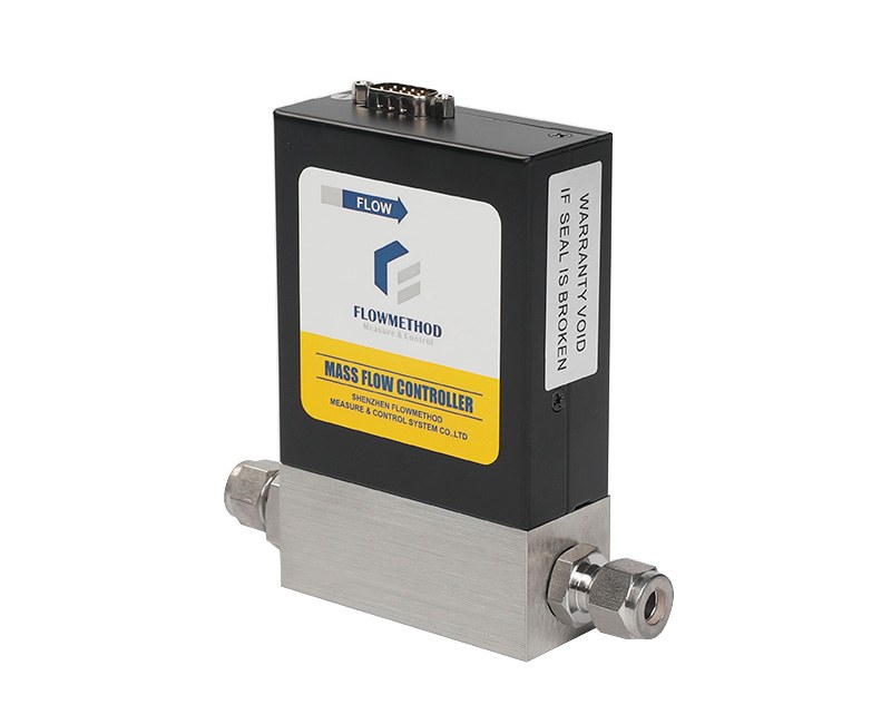
⚠️ Image labelling boundary: the A and D variants of FL-802 share one series photo in our library, so the images here can only be labelled "FL-802 series" and do not show the appearance of either specific model.
How to choose
| Your situation | Suggestion |
|---|---|
| You need the 0.5% FS or 0.1% FS accuracy grade | FL-802-D |
| Your system has an RS485 bus, or you need Modbus RTU | FL-802-D |
| Your system uses analogue signals and 1% FS is sufficient | FL-802-A |
| You only want to know which one is "more accurate" | Only the grade differs; actual accuracy must be confirmed against your conditions |
For gas compatibility, the applicable conditions of each pressure option, the specific interface combination, and which status items the communication can read, please send us the gas type, target flow, working pressure and interface requirements — our engineer will recommend the model and configuration for your actual conditions.
---