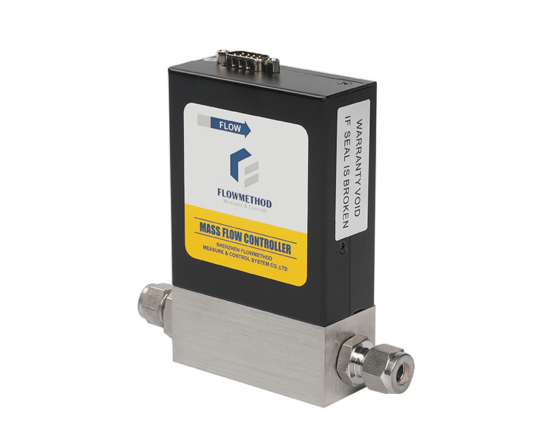
An MFC or MFM nameplate normally identifies the calibration gas, often nitrogen (N₂). If the application instead uses argon, carbon dioxide, methane or a mixture, the reading may require conversion. First identify the model and its configured gas-conversion capability.
Which type of instrument do you have?
A digital model with a built-in gas-factor function: select the actual gas, or enter the agreed factor, through the supported local or host interface. If this function is supported and correctly configured, the displayed flow is the converted actual-gas flow. Do not apply the factor a second time. Confirm that the selected gas matches the medium and that the model supports the required gas data.
An analog-signal model: an output such as 0–5 V or 4–20 mA represents a percentage of the configured full scale. For example, 5 V or 20 mA normally represents full scale. If the actual gas differs from the calibration gas, the same indicated percentage corresponds to a different actual-gas flow. Conversion is then needed in the host software, PLC or calculation.
A digital connector alone does not guarantee automatic gas conversion. Always confirm the supported function for the exact model and firmware.
Conversion formula
Actual flow = indicated calibration-gas-equivalent flow × (actual-gas factor ÷ calibration-gas factor).
For nitrogen calibration, its factor is 1:
Actual flow = indicated flow × actual-gas factor.
In the reverse direction, for a controller:
Nitrogen-equivalent setpoint = target actual flow ÷ actual-gas factor.
A meter has no flow setpoint; only its reading is converted.
Thermal conversion factors depend on the gas properties and instrument design. The following values reproduce the article's reference table. The model-specific coefficient table and agreed calibration conditions take precedence for ordering and measurement.
| Gas | Factor | Gas | Factor |
|---|---|---|---|
| Air | 1.01 | CO₂ | 0.74 |
| O₂ | 0.99 | CH₄ | 0.72 |
| H₂ | 1.01 | N₂O | 0.91 |
| CO | 1.00 | NH₃ | 0.72 |
| Ar | 1.42 | C₂H₆ | 0.48 |
| He | 1.42 | C₃H₈ | 0.35 |
| — | — | SF₆ | 0.26 |
Argon and helium have factors greater than 1 in this table; several multi-atom gases have factors below 1. Even when a factor is close to 1, apply it if the required accuracy makes the difference significant.
Examples in both directions
- Reading to actual flow: with nitrogen calibration, an indicated 100 SCCM while flowing argon corresponds to 100 × 1.42 ≈ 142 SCCM of argon.
- Target to setpoint: to obtain 50 SCCM of CO₂, the nitrogen-equivalent setpoint is 50 ÷ 0.74 ≈ 68 SCCM.
- Range selection: 100 SCCM of CO₂ is equivalent to 100 ÷ 0.74 ≈ 135 SCCM of nitrogen. A 200 SCCM nitrogen-calibrated range puts the normal point at about 68% of full scale, within the suggested 20–80% selection band.
One controller for several gases: convert every range first
Before ordering, convert each gas's minimum, normal and maximum actual flows to the same calibration-gas basis. Check every operating point against the proposed range.
Consider an instrument used alternately for nitrogen purge at 2 SLPM and propane at 30 SLPM:
- A 30 SLPM nitrogen-equivalent range can deliver only about 30 × 0.35 = 10.5 SLPM of propane at full scale. It cannot cover the 30 SLPM propane requirement.
- A range calibrated for 30 SLPM of propane corresponds to about 30 ÷ 0.35 ≈ 86 SLPM nitrogen equivalent. The 2 SLPM nitrogen purge point is only 2 ÷ 86 ≈ 2.3% of full scale, which is a less favorable point for relative accuracy and stable regulation.
A single range may not be a good solution for two very different flow requirements. Prioritize the critical flow, or use separate appropriately sized instruments when other operating points become too low. Actual-gas calibration can improve suitability, but it does not remove the physical range constraint.
For a fixed-composition mixture, use the manufacturer's mixture-factor method. A changing mixture composition cannot be represented reliably by one fixed factor; discuss calibration and measurement strategy with the manufacturer.
Three reminders
- Do not mix coefficient tables from different manufacturers. Sensor design and range can change the factor. A compatible digital model may perform conversion internally; an analog model generally requires host-side conversion.
- Theoretical factors have limits. They are most useful within their validated operating conditions. Significant pressure or temperature departures, or tight accuracy requirements, may call for actual-gas calibration.
- Confirm compatibility and safety first for corrosive or flammable gases. Changing a coefficient does not make an instrument suitable for a different hazardous medium.
When the gas is known before purchase, identify it on the order and confirm the calibration arrangement. See the nitrogen-equivalent flow calculation guide for the website's current selection method.
For selection, installation or technical enquiries, contact Flowmethod: Mr. Dou, +86 180 3818 3381; doufeijin@hotmail.com. See Contact for the full contact list.