
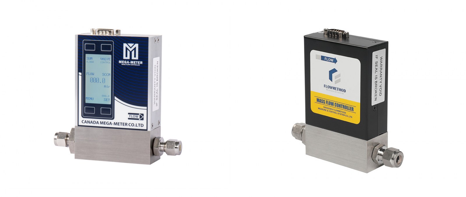
Local Display or an External Display Unit? CM-802LD vs the FL Series
When you select a gas flow controller, one question keeps coming up and is rarely answered properly: where do you read the flow, and where do you set it?
There are two ways to answer it. One builds the display and the keys into the controller itself, so a single unit sets and shows its own values. The other keeps the body responsible for measuring and controlling only, and leaves the display to a separate instrument. The difference is not just one more or one fewer box on the bench — it directly affects how you wire the system, how much bench space you need, and how you add equipment later.
Flowmethod's product line covers both approaches. The CM models use an integrated display (the body carries its own screen), while the FL series puts the display part on an external instrument. The examples below use the 0–10 SLPM band — the most common range — to make the practical differences clear.
1 · Two display forms, one sentence each
Start with how the two official product pages describe their own form.
The CM-802LD page lists "Local operation" and "Local display, setup and remote connection" in the product overview, and its interfaces section states that "CM models use an integrated display". The first application setup is "Local setup & display", its configuration reads "Built-in screen & keys + CM-802LD", the signal line is "Local setpoint & readout · no external controller", and the description is "Set flow with the built-in keys and view it directly on the LCD for intuitive, convenient desktop operation."
The FL-802-A page leads its product overview with "Match your equipment", marked "0–5 V or 4–20 mA analog interface". The body itself carries no display: reading and setting are handled by the external FL-100 instrument. Its first application setup is "Simple desktop setup & display", the configuration is "FL-100 + FL-802-A", and the description is "Use FL-100 to set and display flow for single-channel desktop or on-site operation."
One sentence covers the difference: CM sets and reads on the unit's own screen; FL outputs a signal from the body while the FL-100 handles the display and the setpoint.
2 · Difference 1: who performs the setting and the reading
This is the most substantive difference between the two forms, and the first thing to settle when selecting.
For the CM-802LD, both the setpoint and the readout are completed on the unit itself. The flow is set with the built-in keys and viewed directly on the LCD, and the page states "no external controller". For anyone building a first setup, or commissioning a single channel manually in the lab, that means: once the gas supply and the tubing are connected, there is an interface in your hands — no extra instrument to place on the bench, and no extra cable run to make.
For the FL-802-A, the body only turns the flow into a signal. Its output is 0–5 V or 4–20 mA analog; the setpoint and the readout are taken up by the external FL-100. In the site's "Display Instruments & Accessories" category, the FL-100 entry is listed as "FL-100 display instrument" with the description "Flow setting and display, ready for immediate use."
However, the FL side is not limited to the FL-100. The FL-802-A page gives two further connections: into a PLC analog channel (PLC analog I/O + FL-802-A, "AO setpoint → / AI feedback ←") and Computer + DAQ + FL-802-A ("Analog output setpoint / analog input feedback"). In other words, the display and the setpoint of the FL series can sit on the FL-100, or be handed over to a PLC or a PC.
Likewise, the CM-802LD having a built-in screen does not mean it can only be used locally. Its application setups list two more: "Computer setup & monitoring" (Computer + CM-802LD, "Digital setpoints ↔ flow readout") and "Connect to PLC" (PLC analog or digital control + CM-802LD, "Analog setpoint & feedback / RS485 · Modbus RTU"). The page line "Local display, setup and remote connection" means exactly this.
So the real question is not "integrated display or external display — which is better", but: who do you want to do the setting and the reading most of the time. If you want to work directly at the bench with one less step in the loop, choose the integrated display. If you want the field managed centrally by a PLC or a PC, the local screen is only an extra convenience.
3 · Difference 2: not every integrated display can also be set
This point is easily missed, but it directly affects how you operate the unit.
In the CM family, the controller type (CM-802LD) is set and read on the unit: the application setup is "Local setup & display", described as "Set flow with the built-in keys and view it directly on the LCD".
The meter type (CM-802LD-M) is positioned locally as a readout, not as a control. Its first application setup is "Local flow display", the configuration reads "Built-in LCD + CM-802LD-M", the signal line is "Direct flow readout", and the description is "View flow on the built-in LCD, on a desktop or equipment panel." In the parameter table, CM-802LD carries a "Control range 1–100%" row; the meter type CM-802LD-M carries none, because a meter only reads out and does not set flow.
The FL side follows the same pattern: the first application setup of the FL-802-A-M (gas mass flow meter) is "Desktop flow display", the configuration is "FL-100 + FL-802-A-M", the signal flow is written "Flow signal → display instrument", and the description is "Use FL-100 to display flow for single-channel desktop or on-site readout."
In other words, the display form has two layers: first decide whether the display sits on the body or on an external instrument, then decide whether the unit can be set (controller) or only reads out (meter). CM-802LD and CM-802LD-M are both integrated-display products, but the former can be set locally while the latter only shows the reading.
4 · Difference 3: accuracy grades and communication capability do not follow the display form
The easiest mistake when choosing a form is to assume that switching the display approach leaves the other parameters roughly the same. It does not. Taking the 0–10 SLPM band as the example:
| Item | CM-802LD | CM-802LD-M | FL-802-A | FL-802-A-M |
|---|---|---|---|---|
| Flow range | 0–10 SLPM | 0–10 SLPM | 0–10 SLPM | 0–10 SLPM |
| Accuracy | 1% / 0.5% / 0.1% FS | 1% / 0.5% / 0.1% FS | 1% FS | 1% FS |
| Repeatability | ±0.25% | ±0.25% | ±0.25% | ±0.25% |
| Response | 1 s | 1 s | 1 s | 1 s |
| Control range | 1–100% | / | 1–100% | / |
| Temp. | −10–60 °C | −10–60 °C | −10–60 °C | −10–60 °C |
| Signal | RS485/Modbus + analog | RS485/Modbus + analog | Analog 0–5 V / 4–20 mA | Analog 0–5 V / 4–20 mA |
| Supply voltage | 9–36 VDC | 9–36 VDC | 9–36 VDC | 9–36 VDC |
| Power consumption | 5 W | 5 W | 4 W | 4 W |
| Dimensions | 76 × 36 × 126 mm | 76 × 36 × 126 mm | 76 × 36 × 126 mm | 76 × 36 × 126 mm |
The "Signal" column is abbreviated. Full meaning: CM-802LD / CM-802LD-M provide a local screen for setting and reading, plus RS485 and MODBUS RTU digital communication and 0–5 V / 4–20 mA analog; FL-802-A / FL-802-A-M provide only 0–5 V or 4–20 mA analog output, with no digital communication.
FS means full scale. Accuracy is specified relative to full scale; confirm the accuracy option, the calibrated range and the interface configuration against the order documentation.
The figures listed for CM-802LD-M and FL-802-A-M are the same as those of the corresponding non-M models in the same series: -M is the meter-type variant of that series (flow band, accuracy grades, repeatability, response time, operating temperature, supply voltage and power consumption are identical to the controller type of the same series).
"/" means that the item does not apply to the -M meter type — a meter only reads out and cannot be set, so it has no control range.
Please confirm against the documentation for the exact model before ordering.
Three points in the table deserve separate mention:
First, accuracy comes in two tiers, independent of the enclosure form. CM-802LD and CM-802LD-M both offer 1% / 0.5% / 0.1% FS, while FL-802-A and FL-802-A-M offer 1% FS only. If your working conditions call for 0.5% FS or 0.1% FS, the two FL models cannot meet that, and the selection has to be made on the CM side. One reminder while you are at it: ±0.25% is the repeatability, not an accuracy grade — do not mix the two figures when ordering.
Second, communication capability also comes in two tiers. The signal and operation entry of both CM-802LD and CM-802LD-M reads "Local display + RS485, MODBUS RTU, 0-5V/4-20mA", that is, digital communication comes together with the local display. For FL-802-A and FL-802-A-M, the same entry lists only "0–5 V or 4–20 mA": an analog-output-only meter, with no separate digital communication option in that column. If the installation needs several units on one network or a digital link, this item has to be checked at the same time.
Third, the power consumption differs by 1 W. The CM-802LD parameter table lists 5 W, the FL-802-A lists 4 W. It is a small difference, but with many channels densely installed in one cabinet, the accumulated consumption has to be counted into the supply headroom.
5 · Difference 4: the external display option is more than one instrument
Choosing the FL route does not mean the display end has to be the FL-100.
In the site's "Display Instruments & Accessories" category, besides the FL-100 display instrument there are "Touchscreen control" (description: "Touchscreen control, with software tailored to your needs.") and "FL-4000x four-channel controller" (description: "Four-channel integrated control, expandable by cascading."), together with fittings and mixing chambers. The reading given by the page itself is: "Choose the supporting category you need, from display and multi-channel control to gas connections. Then match interfaces and configuration to your equipment."
One point has to be stated: this article quotes the category facts only, and makes no assertion that a given FL model pairs with a given instrument. If your requirement is multi-channel, and the number of devices to connect and the interface types involved are on a different scale from a single FL-100 desktop unit, then the actual configuration needs to be checked with our engineer.
6 · Selection quick reference
You want to set and read directly on the unit, with as few extra devices as possible → CM-802LD (controller type, locally settable)
You want to read on the unit and not set it locally → CM-802LD-M (meter type, local display only)
You want the body to output an analog signal only, with setting and display handed to an external instrument → FL-802-A + FL-100, or FL-802-A-M + FL-100
You want the field managed centrally by a PLC or a PC, with the local screen only a convenience → CM-802LD still connects to a PLC (analog setpoint and feedback / RS485 · Modbus RTU) or to a computer
You need 0.5% FS or 0.1% FS accuracy → select it on CM-802LD / CM-802LD-M; the two FL models offer 1% FS only
You need RS485 / MODBUS RTU digital communication → likewise on the CM side; the signal and operation entry of the two FL models lists only 0–5 V / 4–20 mA
You need a multi-channel or touchscreen solution → this falls under accessory selection (which models the touchscreen controller and the FL-4000x four-channel controller support has to be checked with our engineer against the actual configuration)
Manuals, dimensional drawings and protocol documents should be confirmed for the exact model. If you already have a clear gas type, flow range and working pressure, send us your conditions — our engineer can check which series and configuration fit.
For selection, product documentation or technical enquiries, contact Shenzhen Flowmethod Measure & Control Systems Co., Ltd.:
Contact: Mr. Dou | Tel: +86-18038183381
Email: doufeijin@hotmail.com | Website: www.flowmethod.net