
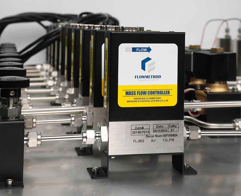
The most common on-site complaint about a mass flow controller is "the flow is wrong" — the setpoint and the actual flow do not match, the reading keeps counting after the valve closes, or the reading jumps around. In most cases the instrument itself is fine; the real issue is a messy troubleshooting order: people suspect the sensor first, take things apart for a long time, and finally find the gas supply was off or a fitting was leaking.
This article lists the most common on-site problems as a quick-reference encyclopedia. Each item gives "symptom → check first → typical cause", clearing the zero-cost items first, then working down through gas path, installation, medium, and setpoint, to save time.
1. Set the general principle first: external before internal
Among on-site "flow is wrong" cases, the share that truly needs factory return is low. Check in this order; most problems are solved in the first two steps:
1. Gas path external: gas source, valves, line leaks, fittings — zero cost, zero disassembly.
2. Installation and medium: flow direction, straight runs, particles, water, gas type.
3. Setpoint and reading: set value, zero point, range, signal interference.
4. The instrument itself: only when everything above is normal do the valve seat and sensor come into play.
Each category below follows this order, so you do not start by taking the instrument apart.
2. Won't fully close: valve does not seat, flow remains at zero setpoint
"Won't seal / won't fully close" is one of the most easily misjudged categories in long-term operation. First separate three presentations (wrong classification turns a ten-minute fix into a factory return):
- Fails to close completely: after a close command the reading holds at a noticeable value and does not drop over time — usually a foreign object stuck in the valve seat or the valve core not landing on the seal.
- Slow creep after closing: drops to zero at the moment of closing, then slowly rises over a few minutes — first suspect zero drift or a small downstream back-pressure.
- Reading not zero but no actual flow downstream: a soap test confirms no gas downstream; the problem is on the display side, a zero offset.
(For the three causes of valve-seat deposits, back-pressure and differential pressure, see the dedicated article on why a mass flow controller won't seal, with a cause-by-cause breakdown.) Below is an analog zero-offset instance that the other article does not expand on but is common on-site:
A concrete numeric instance: setpoint is zero yet it will not fully close
Thermal gas mass flow controllers usually take a 0–5 V analog setpoint. When the setpoint is 0, there should be no drive output at all. But if the analog channel has a zero offset, the voltage the controller actually detects may not be 0.
For example, the setpoint input is measured at 80 mV. With a 5 V full scale:
80 mV ÷ 5000 mV = 1.6% (full scale)
Most models set a "minimum valid setpoint threshold" in firmware, roughly at the 1% FS level: commands below this threshold are treated as 0 and the valve stays fully closed; commands above it are judged as a valid setpoint and the valve opens to the corresponding position.
Since 1.6% > 1%, the controller executes this "zero setpoint" as a 1.6% valid setpoint — the valve opens about 1.6%, appearing as "won't fully close".
The usual cause is an electrical zero offset of the analog channel: the controller and valve driver share a reference ground, grounding is poor, or the signal line picks up crosstalk, lifting the 0 V reference by about 80 mV. Troubleshooting order:
1. Measure the setpoint input voltage to confirm whether it is 0 V or 80 mV.
2. Check the grounding and shielding of the analog wiring; separate the controller ground from the power ground.
3. Perform a zero calibration to push the offset below 1% FS so the zero setpoint is recognized as 0.
(Note: the 1% threshold and 80 mV above are illustrative; the exact threshold varies by model and circuit. Confirm with an engineer when in doubt.)
3. Low flow: cannot reach the setpoint
Symptom: the setpoint is maxed out, but actual flow will not rise or rises very slowly.
- First check the gas source: is upstream pressure sufficient, is the shut-off valve fully open, is the regulator set too low — many "won't rise" cases are simply insufficient upstream supply.
- Then check the line: is the outlet blocked, is downstream equipment consuming most of the pressure drop.
- Then confirm the setpoint itself was actually delivered: at 100% setpoint, especially on an analog channel, verify the signal actually sent is truly 100% — a 5 V setpoint means 100%, but if the measured command is only 4.95 V the controller is actually running at 99%. It looks like low flow, but the setpoint was never fully given.
- Finally the range: is the operating point in a very low part of full scale, or does the gas differ greatly from the calibrated gas, leaving insufficient usable pressure ratio.
4. Inaccurate reading, no zero return, jumping
Three reading problems have different causes; do not lump them together:
- Systematic inaccuracy: first confirm whether you are reading the setpoint or the measured value, and that the unit (SCCM / SLPM) is consistent; then check whether the gas type matches the calibrated gas (see section 6 for conversion).
- No zero return: first rule out medium residue and power-up settling time, then perform zero calibration.
- Jumping: almost always a signal problem — poor grounding and shielding, signal line run parallel to power lines, unstable supply. Shield properly and keep away from power lines first, then check the supply.
5. Reverse installation, leaks, fitting hazards
- Flow direction: a mass flow controller has a specified flow direction; reverse connection directly affects measurement and valve action. Check the flow arrow on the housing before installation.
- Leak test: a hissing sound on the gas line or pressure drop during a hold test is, nine times out of ten, a leaking fitting or line, not the instrument. Apply neutral soap solution to ferrule joints, threads and valve stems; bubbles mark the leak. For clean or high-vacuum scenarios use helium mass-spectrometer leak detection.
- Straight runs and vibration: keep enough straight pipe, away from nearby elbows and valves; strong vibration and heat sources change the operating condition. Long signal cables should be shielded and kept away from power lines.
(For how to install ferrules in six steps, see the dedicated article; for whether a crooked installation affects accuracy, see the dedicated article.)
6. Change the gas type and the reading drifts
Mass flow meters and controllers are shipped calibrated for a specified gas (such as nitrogen). When another gas is used on-site, apply the conversion factor; do not use the original calibrated reading directly.
Conversion is a "medium property" issue, not a broken instrument. The conversion factor comes from gas physical properties (density, specific heat) and differs markedly between gases; when in doubt, confirm with an engineer based on the actual gas — do not force-fit from experience.
7. Digital (-D) communication lost or not updating
The -D model uses RS485 / Modbus RTU; troubleshooting differs from the analog type:
- Whether the communication address and baud rate match the host.
- Whether the A/B lines are reversed and the termination resistor is configured per bus length.
- Whether the supply and grounding are stable.
For communication issues, check wiring and parameters first, then suspect the module.
8. One table: symptom → check first → deep dive
| On-site symptom | Check first | Deep dive |
|---|---|---|
| Flow will not rise | Gas source, valve, upstream pressure | Supply and pressure drop |
| Hissing, pressure drop on hold | Fitting and line leaks | Ferrule installation |
| Flow disagrees with calibration | Flow direction, straight run, vibration | Installation direction |
| Flow remains at zero setpoint | Valve-seat particles, back-pressure, analog zero offset | Won't fully close (incl. 80 mV zero-offset instance) |
| Systematic reading offset | Unit, gas type | Gas conversion |
| Jumping / no zero return | Grounding, shielding, supply | Inaccurate reading |
| Digital no response | Address, baud rate, A/B lines | Communication config |
Fix the troubleshooting order and most on-site "flow is wrong" cases are solved in the first two steps — saving labor and avoiding unnecessary instrument swaps. Flowmethod gas mass flow controllers and mass flow meters cover ranges from milliliters to hundreds of liters; selection and on-site support can be confirmed with an engineer based on the actual operating condition.
For selection, product documentation or technical enquiries, contact Shenzhen Flowmethod Measure & Control Systems Co., Ltd.:
Contact: Mr. Dou | Tel: +86-18038183381
Email: doufeijin@hotmail.com | Website: www.flowmethod.net