
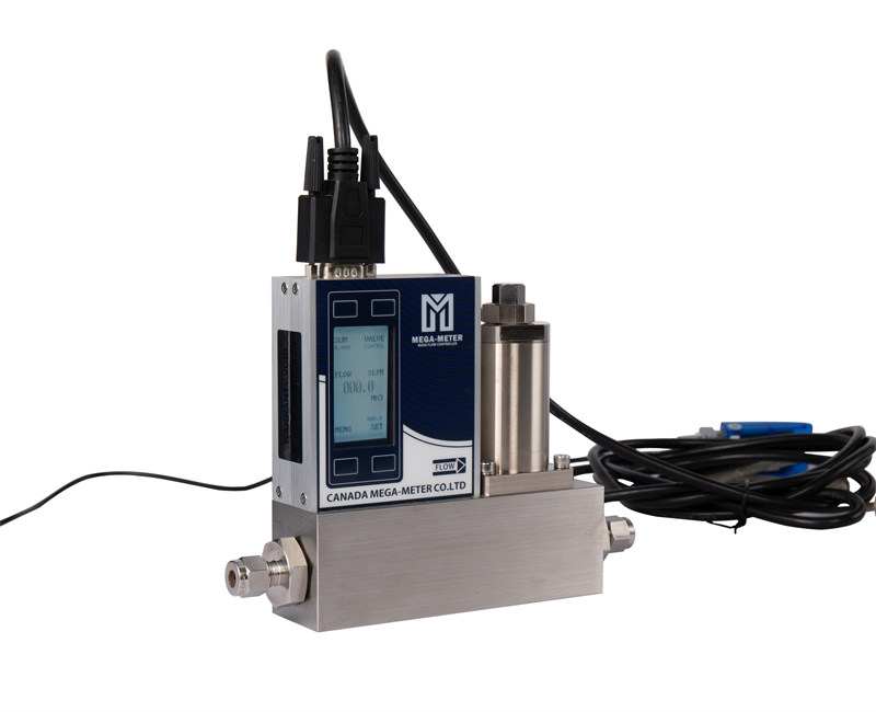
Zero drift, residual flow at a zero command, or a changing gas mixture can result from dust, condensate or oil in the gas path. Thermal instruments measure through heat transfer, so contamination can change the sensing conditions or damage a valve even when the electronics still operate.
1. Three vulnerable areas
Sensor passages: small bypass channels and capillaries can collect particles or oil films. This changes heat transfer and may shift zero or calibration; the direction of the error depends on the contamination and design.
Control valve: a particle at a precision sealing surface can prevent closure. Repeated zero adjustment will not remove it. This valve-related issue applies to controllers, not valve-free meter models.
Seals and flow passages: thread debris or deteriorating seal material can travel downstream and obstruct small passages, gradually changing performance or causing damage.
2. Different contaminants require different measures
- Particles: dust, metal fragments, seal debris and degraded filter material can cause gradual damage that resembles normal aging.
- Liquid water: condensation or carryover can cause sudden zero shifts, corrosion or sensor damage.
- Oil mist or film: compressor oil, assembly contamination and residues may change heat transfer and trap more particles.
Filtration, drying and oil removal are separate controls; one does not replace the others.
3. Upstream filtration
Place suitable filtration before the instrument and avoid unnecessary unfiltered tubing between the filter and inlet. Check the dew point, low points where liquid collects, and appropriate oil-removal stages.
The original article uses 5 μm industrial filtration and finer staged filtration down to 0.01 μm in some applications as examples. They are not universal requirements. Select filter type, rating, gas compatibility, pressure loss and cleanliness performance with the instrument and filter suppliers. A nominal particle rating alone does not establish gas suitability.
Record the initial filter pressure drop and its trend. A rise to roughly twice the initial value can be a maintenance observation, but replacement should follow the filter manufacturer's limits, the flow and the available instrument pressure differential—not a universal “two times” rule.
4. Tube diameter and gas velocity
For a 4 mm internal diameter tube, dividing volumetric flow by cross-sectional area gives the following approximate values:
| Nitrogen volume flow | Approximate average velocity |
|---|---|
| 6 L/min | 8.0 m/s |
| 12 L/min | 15.9 m/s |
| 24 L/min | 31.8 m/s |
These values assume the listed volume flow applies at the tubing's actual conditions. If the input is SLPM, first convert it to actual pipe volume flow using absolute pressure, temperature and the relevant gas relationship. The table must not be applied unchanged to every pressurized gas line.
Undersized tubing can increase pressure loss and noise and transport contaminants more readily. Evaluate tube sizing and pressure loss for the actual process instead of continually increasing source pressure.
5. Routine preventive checks
- Use the approved cylinder-change and purge procedure; keep unused ports capped. Do not vent hazardous gases as an informal cleaning method.
- Trend filter pressure drop and maintain the elements before a restriction disrupts operation.
- Follow a suitable purge and dry-storage procedure before a long shutdown.
Repeated zero drift, residual controller flow at zero command, or increasing disagreement between comparable instruments should prompt an upstream cleanliness check. Provide the results to the manufacturer; do not dismantle a thermal sensor in the field.
Protect the instrument with appropriately selected filtration, drying and oil control. Calibration intervals should follow the application and documented maintenance plan.
For selection, installation or technical enquiries, contact Flowmethod: Mr. Dou, +86 180 3818 3381; doufeijin@hotmail.com. See Contact for the full contact list.