
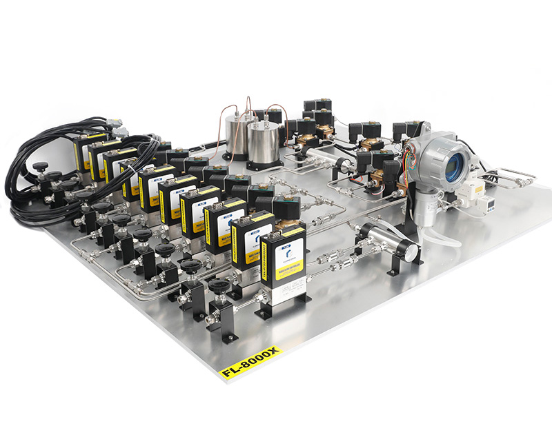
Putting an MFC on each gas channel and setting a flow ratio is a sound starting point for dynamic gas mixing. It does not by itself prove that the intended concentration reaches the sampling point. Six engineering issues lie between the setpoints and the sample: concentration span, gas switching, response, humidity, control strategy and low-concentration adsorption.
An MFC is a mass flow controller; an MFM is a mass flow meter. A meter reports flow but cannot independently regulate a mixing channel. The following design process distinguishes those roles.
1. Concentration span: one range may not cover ppm to percent
A requirement from a few ppm to thousands of ppm or percent levels can span three or four orders of magnitude. Two constraints matter.
Accuracy relative to full scale. With a specification such as ±1% FS, a very low source-channel operating point can have a large relative uncertainty. Divide a wide concentration requirement into suitable flow ranges and keep routine points in a useful part of each range—about 20–80% is a selection target, subject to the actual specification.
Dilution ratio. For a source gas diluted with a gas that does not contain the target component, on a consistent flow/concentration basis:
Target concentration = source-gas concentration × source-channel flow ÷ total flow.
At high dilution, source flow becomes small and its uncertainty matters more. The source concentration's relative uncertainty also contributes to the result; dilution does not remove it. Rather than expecting one stage to cover a 1000-fold change, consider two stages with an intermediate concentration, each operating in a suitable range.
Low-concentration hardware can cost more because small passages, valve behavior, leakage and dead volume become critical. Range division should place the required performance where it is needed. Sharing occasional-use bands and dedicating a range to the normal concentration band may be more economical than one oversized compromise.
2. Multiple gases and switching: residual gas matters
A multi-channel system may handle conventional, corrosive, humid or condensable gases.
Materials first: check chambers, tubing, valves and seals against each medium. Where appropriate, separate corrosive channels from conventional ones. Shared segments can cause both contamination and material exposure.
Then residual gas: old gas remains in dead spaces, valve cavities, fitting gaps and on adsorbing surfaces. If the target is 10 ppm, residual background of tens of ppm cannot be ignored just because the selector valve has changed position.
Use an approved sequence: replace the old gas → purge with a compatible gas → wait for confirmed concentration stability. Estimate purge time from volume divided by actual-condition purge flow, then allow the validated number of exchanges. Low-concentration work may need additional equilibration for adsorption and dead spaces.
Check valves can prevent backflow but also add restriction and dead volume. Use them where the design requires them rather than adding unnecessary valves without evaluating response and purging.
3. Response: transport delay and exchange time
A changed setpoint must pass through tubing, mixing chambers, fittings and valves before it reaches the sample. Response includes transport delay and replacement of the previous mixture.
For an effective volume of 100 mL and an actual-condition total flow of 1 L/min, one nominal exchange takes 6 seconds. Three exchanges take about 18 seconds, close to 20 seconds. At 100 mL/min, one exchange takes 1 minute, so several exchanges take minutes.
These are planning estimates, not proof of homogeneous concentration. If flow is given in SLPM, convert it to volume flow at the chamber's pressure and temperature before comparing with the physical volume. Mixing behavior and adsorption also affect settling time.
Where a staged design is needed, an initial principal dilution can reduce a large concentration difference before adding small, finely controlled components. Confirm the arrangement for the particular process. More mixing stages can improve mixing but each adds volume and delay; use enough stages, not the greatest possible number.
Uniformity depends on internal structure and the sampling position, not simply a large chamber. Static mixing elements or baffles may help. Take the sample after sufficient mixing, and include filters and protective valves in the response-volume budget.
4. Humidity: placement and concentration basis
For thermal flow products specified for dry-gas service, condensate or droplets can change heat transfer, contaminate a valve or damage the sensor. Keep humidification downstream of the dry-gas measuring/control channels unless a specific instrument has been approved for the wet medium. Mix the dry gases first, then add the required moisture.
Common approaches have different tradeoffs:
- Bubbling/saturation: relatively simple, with humidity influenced by water temperature; account for lag and droplet carryover.
- Membrane humidification: separates gas and liquid, with response depending on membrane and system design.
- Vapor injection: permits controlled water-vapor addition but requires suitable temperature control and vaporization equipment.
Choose according to humidity accuracy, permitted settling time, material compatibility and maintenance.
Adding water vapor also changes the concentration basis. A dry-basis concentration excludes water from the total; a wet-basis concentration includes it. Agree the basis before specifying or accepting a system.
Keep humid gas lines above the relevant dew point, within component temperature limits, to prevent condensation. A multi-channel temperature/humidity-controlled mixing system can coordinate dry-side ratios and downstream humidity, but the detailed functions must be agreed for the supplied configuration.
5. Open-loop or concentration feedback?
Many systems use a concentration calculated from commanded flow ratios without measuring and correcting the final concentration. This is open-loop concentration control, even when each MFC has its own internal flow-control loop.
The calculation assumes that component concentrations, actual flow, leakage and the gas path remain as expected. A drifting channel, small leak or sticking valve can cause the sample concentration to differ from the calculation without automatically identifying the difference.
An analyzer at the appropriate point can measure concentration and support feedback correction. It adds three design considerations:
- Its own range, accuracy, response, calibration and maintenance form another measurement chain.
- Mixing volume and transport delay complicate controller tuning; too much correction can cause oscillation, too little can respond slowly.
- Humidity can affect sampling and analysis, and condensation can introduce another error source.
A practical design may combine calculated flow ratios with measurement at critical low-concentration or high-value points, using calibration records and periodic checks to verify the underlying assumptions. Closed-loop concentration control is not automatically “better”; its benefit must justify the added cost and complexity.
6. Adsorption at low concentration
Gas-path surfaces can adsorb and later release components. This is particularly important for ammonia, hydrogen sulfide, sulfur dioxide, water vapor and some VOCs. Nitrogen and argon often present smaller adsorption problems. Hydrogen is not an inert gas; its safety, permeation and small-leak behavior require their own assessment.
A 1 ppm ammonia stream through an unsuitable, unconditioned line may initially reach the outlet below its target. Concentration can rise as surfaces equilibrate, and later desorption can cause a tail after switching gas. The behavior depends on concentration, temperature, material and prior exposure.
One fixed offset such as “add 0.2 ppm” cannot generally correct all operating conditions. First make the loss repeatable, then determine whether a controlled correction is justified.
Four design measures
- Select compatible low-adsorption surfaces, such as an appropriate electropolished or inert-coated material, or suitable PFA tubing, after assessing the gas and process requirements.
- Minimize tubing length and dead spaces, and choose flow/volume to reduce residence time.
- Define a purge and equilibration step and confirm stability at the actual sampling point before taking data.
- Validate using a reference gas near the target concentration or a suitable online analyzer, rather than estimating a correction by feel.
Existing piping: five steps before compensation
- Precondition and equilibrate. Use a gas close to the target concentration at the working flow until the sampling-point measurement stabilizes. The original article mentions tens of minutes as an example; the measured behavior determines the actual duration. Compensation only makes sense once the loss is repeatable.
- Measure at the sampling point. Compare the target and delivered concentration there, not only at the instrument outlet. If 1.00 ppm commanded gives 0.93 ppm, a proportional first estimate is 1.00 ÷ 0.93 ≈ 1.075, or a command near 1.07–1.08 ppm. Verify the new result rather than accepting the arithmetic alone. Document concentration, flow, temperature and line condition.
- Calibrate at several points. Adsorption is not necessarily proportional to concentration. The guide suggests two or three points in each low, middle and high band, with an agreed interpolation method, rather than extending one multiplication factor across the full range.
- Revalidate when conditions change. A changed flow, overnight shutdown, temperature change or piping change can invalidate the correction. Document conditioning, sampling-point validation, permitted correction and scheduled rechecks.
- Reject nonrepeatable compensation. If repeated tests at the same conditions give inconsistent loss, improve the gas-path design. More aggressive numerical correction does not make an unstable adsorption process traceable.
Design comes before compensation: reduce and stabilize the loss, then validate any correction under defined conditions.
7. Put the six issues into one design sequence
- Define lowest, highest and normal target concentrations to select flow bands and dilution stages.
- List gases and switching combinations to choose materials, separated paths and purge procedures.
- Set allowable settling time to determine volume, mixing stages and sampling arrangement.
- Define humidity and dew-point requirements, humidification placement and temperature control.
- Choose concentration-monitoring or feedback points and the control strategy.
- Validate the low-concentration endpoint, including materials, equilibration and reference comparison; use compensation only if its conditions and repeatability are established.
Only then compare the detailed range, materials, connections and custom structure with the supplier. Accurate mixing is established during design and validation, not by adjusting ratios after an unsuitable gas path has been built.
Related reading: six-step flow-product selection, custom gas mixing systems, and fittings and mixing chambers.
For selection, installation or technical enquiries, contact Flowmethod: Mr. Dou, +86 180 3818 3381; doufeijin@hotmail.com. See Contact for the full contact list.