
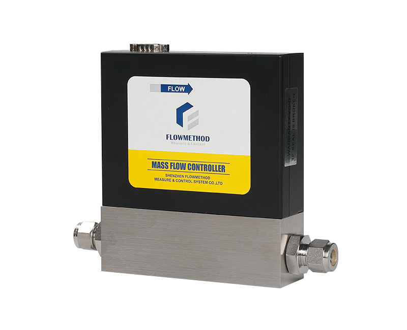
“Not closing completely” can describe several different symptoms. A nonzero reading is not automatically valve leakage. Separate a real gas flow from zero drift, a residual command or an unsuitable pressure condition before deciding that the controller needs repair.
1. Identify the actual symptom
Persistent flow after the close command: a stable, appreciable downstream flow may indicate contamination at the valve seat or failure to reach the closed position.
A reading that slowly rises after closure: investigate zero drift, changing pressure, trapped volume or backflow as well as leakage. The trend alone does not identify the cause.
A nonzero display without independently confirmed downstream flow: this can be a zero-offset issue. Use an appropriate measurement method to determine whether gas is actually moving; a display reading alone is not a leak test.
For comparison, log readings for 5 minutes, at 30-second intervals, under recorded supply pressure, outlet conditions and a confirmed zero command. The original article's 3-minute / 0.5% FS rule must not be treated as a general valve-leak acceptance limit. Zero stability and leak tightness are different specifications. Assess leakage using the manufacturer's applicable method and limit.
2. Deposits and condensation at the valve
A precision valve seat is sensitive to:
- Particles from tube preparation, assembly or deteriorating seals.
- Condensable components that form liquid or oil films at cooler surfaces.
- Reaction products deposited by the process gas on the seat or seals.
First check that upstream filtration is correctly installed and maintained and that an unintended bypass is not open. Then use the manufacturer's approved purge procedure, if appropriate for the medium and condition. If closure remains abnormal, request manufacturer cleaning or assessment. Field disassembly can scratch the sealing surfaces and damage performance.
3. Residual command and zero offset
A previous program step may leave a small command active. An analog channel may retain an unintended voltage/current or receive interference. Confirm the actual command at the instrument, not only the displayed software target.
For 0–5 V, the zero-flow command is the specified zero voltage. For 4–20 mA, zero flow is normally represented by 4 mA, not 0 mA; follow the exact input definition.
Then establish true no-flow conditions and stable temperature before evaluating zero. Record readings before and after an authorized zero adjustment. If the result still changes, investigate the remaining conditions rather than repeatedly recalibrating zero to hide a problem.
4. Backpressure and differential pressure
Compare inlet, outlet and differential pressure with the ordered operating envelope. Backpressure or reverse pressure can affect valve operation and the observed flow; the closing mechanism and allowed direction depend on the actual valve design.
An engineer-approved isolated test with a stable supply and suitable downstream arrangement can distinguish an instrument issue from a system issue. An open-to-atmosphere outlet is only suitable when the gas, pressure and discharge conditions permit it. Hazardous gases require appropriate collection or treatment, not uncontrolled venting.
An MFC's regulating valve must not be assumed to provide the function of a certified process safety shutoff or independent isolation valve.
5. Keep a consistent diagnostic record
- Five-minute reading sequence, every 30 seconds.
- Actual command signal measured at the instrument.
- Inlet and outlet pressure and any reverse-pressure conditions.
- Zero readings before and after an authorized adjustment.
- Results of the approved isolated test and its discharge arrangement.
- Filter maintenance and purge history.
6. Prevention
Maintain filtration before failure occurs. Address condensation through gas-path design and approved temperature control, within component limits. Purge appropriately before prolonged shutdown.
Choose the calibrated range for actual use; a normal point around one-fifth to four-fifths of full scale is a useful selection target. Valve size and flow passages vary with the range, but neither a low reading nor a particular selected range proves shutoff leak performance.
Related reading
- Double-ferrule fitting installation.
- Troubleshooting inaccurate or unstable readings.
- Gas-path leak testing.
Check command → system conditions → instrument, in that order. Provide the engineer with the gas, range, pressure and piping arrangement before attempting repeated disassembly.
For selection, installation or technical enquiries, contact Flowmethod: Mr. Dou, +86 180 3818 3381; doufeijin@hotmail.com. See Contact for the full contact list.